Reliable field acquisition
Collect 32 control and status signals from sensors, switches, relays, and other digital field devices in one compact module.


N132x digital input modules provide 32 isolated input channels. Select low-level triggered, high-level triggered, or dry-contact input according to the field signal and common-terminal wiring.
Acquire status signals from sensors, switches, relays, and dry contacts with clear power and per-channel LED indication.
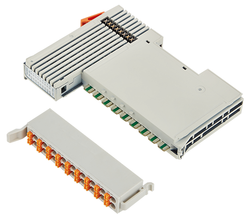
Models, input logic, wiring requirements, electrical isolation, environmental ratings, dimensions, terminal assignment, and N-Series system compatibility.
N1321 is low-level triggered, N1322 is high-level triggered, and N1323 is designed for dry-contact input.
| Selection point | N1321 | N1322 | N1323 |
|---|---|---|---|
| Input type | Low-level triggered | High-level triggered | Dry-contact input |
| Logic 1 | +15 to +30 VDC | +15 to +30 VDC | Input shorted to COM |
| Logic 0 | -3 to +5 VDC | -3 to +5 VDC | Input disconnected from COM |
| Common terminal | Connected to power positive | Connected to 0 VDC | Used for contact closure |
| Channels | 32 channels | 32 channels | 32 channels |
Electrical and indication data for N1321, N1322, and N1323.
Connection and mounting data for panel integration.
Operating limits and industrial protection information.
Physical dimensions and requirements for an N-Series station.
Collect 32 control and status signals from sensors, switches, relays, and other digital field devices in one compact module.
Two red power indicators and 32 green input LEDs make power and logic status easy to verify during commissioning and troubleshooting.
N132x is an optional module for the N-Series distributed I/O system and must be used with a suitable fieldbus coupler, such as a BL210 Series coupler.
The N132x combines 32 digital input channels, three signal versions, individual channel LEDs, 2 kVrms isolation, spring-cage wiring, and industrial EMC protection.
Acquire DI1 to DI32 control and status signals from industrial field devices in a compact 28.4 mm-wide module.
Select N1321 for low-level triggering, N1322 for high-level triggering, or N1323 for dry-contact signals.
Connect solid, stranded, or fine-stranded conductors from 0.3 to 2.5 mm² using secure spring-cage terminals.
2 kVrms isolation, IP20 protection, EMC protection, and -20°C to 55°C operation.
N1321 provides low-level triggered input, N1322 provides high-level triggered input, and N1323 accepts dry-contact signals.
N1321 · Low-Level Trigger
Designed for 32-channel low-level triggered digital input. Logic 1 is +15 to +30 VDC and logic 0 is -3 to +5 VDC.
Use the defined DI, COM, and PE terminals, then install the module on a compliant DIN-35 rail as part of the N-Series station.
The N-Series includes digital input, digital output, analog input, analog output, RTD, temperature, pulse, and power modules.
I/O modules can be arranged in different combinations within the distributed I/O station without grouping them by module type.
6 modules
Digital input options for NPN, PNP, and dry-contact sensing.
5 modules
Digital and relay output options for discrete control.
3 modules
Analog input options for current and voltage acquisition.
2 modules
Analog output options for current and voltage control.
4 modules
RTD modules for PT100 and PT1000 temperature sensing.
2 modules
Dedicated temperature modules for NTC and thermocouple signals.
3 modules
Pulse counting and pulse-output control modules.
1 module
Additional power support for larger N-Series stations.
When the number of selected N-Series I/O boards exceeds 20, an additional power module is required. If the number is less than 20, no extra power module is needed.
N132x fits distributed I/O installations that require compact, isolated 32-channel acquisition of voltage-level or dry-contact signals.
Use the individual DI indicators to check field status and quickly locate sensor or wiring problems.
Select the correct low-level, high-level, or dry-contact version for each field-device wiring requirement.
Standardize sensor, switch, relay, and dry-contact monitoring in machines and automation equipment.
Use N132x with a suitable N-Series fieldbus coupler, such as a BL210 Series coupler.